
Toyota Error Codes - Engine, Automatic Transmission, SRS, ABS and 4WS
TOYOTA - OBD-I and OBD-II Self-Diagnosis
Toyota error codes Download pdf
Toyota Diagnostic Trouble Codes Full List-ObdII365 Download
How to read ECU fault codes. 1KZ-TE & D4D Download
ENGINE:
Self-diagnosis codes are read by the number of flashes of the "CHECK ENGINE" indicator when the terminals "TE1" - "E1" of the DLC1 connector under the hood are closed


or "TC" - "CG" of the DLC3 connector under the dashboard with the ignition on.
12 - Crankshaft position sensor (P0335)
13 - Crankshaft position sensor (P0335, P1335)
14 - Ignition system, coil No. 1 (P1300) and No. 4 (P1315)
15 - Ignition system, coil No. 2 (P1305) and No. 3 (P1310)
16 - Automatic transmission control system
18 - VVT-i system - phases (P1346)
19 - Accelerator pedal position sensor (P1120)
19 - Accelerator pedal position sensor (P1121)
21 - Oxygen sensor (P0135)
22 - Coolant temperature sensor (P0115)
24 - Intake air temperature sensor (P0110)
25 - Oxygen sensor - lean mixture signal (P0171)
27 - Oxygen sensor No. 2
31 - Absolute pressure sensor (P0105, P0106)
34 - Turbocharging system
35 - Turbo boost pressure sensor
36 - CPS Sensor (P1105)
39 - VVT-i System (P1656)
41 - Throttle position sensor (P0120, P0121)
42 - Vehicle speed sensor (P0500)
43 - Starter signal
47 - the position sensor of the additional throttle valve
49 - Fuel pressure sensor (D-4) (P0190, P0191)
51 - State of switches
52 - Knock sensor (P0325)
53 - Knock signal
55 - Knock sensor No. 2
58 - SCV drive (D-4) (P1415, P1416, P1653)
59 - VVT-i signal (P1349)
71 - EGR system (P0401, P0403)
78 - injection pump (D-4)
89 - ETCS drive (P1125, P1126, P1127, P1128, P1129, P1633)
92 - Cold start nozzle (D-4) (P1210)
97 - Injectors (D-4) (P1215)
98 - Vacuum sensor in the vacuum brake booster (C1200)
Automatic transmission:
Self-diagnosis codes are read by the number of flashes of the "O / D OFF" indicator when the terminals are closed
"TC" - "CG" (13-4) of the DLC3 connector under the dashboard and the ignition is on
(In this case, the inclusion of an overdrive must be allowed - "O / D OFF" does not light up).
11 - Norm
37 - Automatic transmission input shaft speed sensor (P1705)
38 - Automatic transmission working fluid temperature sensor
42 - Speed sensor (or output shaft speed sensor) (P0500)
44 - Speed sensor (or rear output shaft speed sensor)
46 - Accumulator pressure control solenoid (P1765)
61 - Speed sensor (or front output shaft speed sensor)
62 - Solenoid No. 1 (P0753)
63 - Solenoid number 2 (P0758)
64 - Solenoid of the torque converter lockup clutch (P0773)
67 - Automatic transmission input shaft speed sensor
68 - Solenoid control of the torque converter lock-up clutch
73 - Solenoid of the center differential lock clutch
Diagnostics of the ABS system:
Reading codes (models with DLC3 connector) (OBD-II)
- Jumper the terminals "TC" (13) and "CG" (4) of the DLC3 connector.
- Switch on the ignition.
- After 4 seconds, read the code by the number of indicator flashes.
- Remove the jumper from the "TC" and "CG" terminals.
Resetting codes (models with DLC3 connector)
- Jumper the terminals "TC" (13) and "CG" (4) of the DLC3 connector.
- Switch on the ignition.
- Press the brake pedal eight or more times within three seconds.
- The indicator should display the code of the norm (blink 2 times per second).
- Remove the jumper from the "TC" and "CG" terminals.
11 - Relay e / m valve (open circuit)
12 - Relay e / m valve (short circuit in the circuit)
13 - Electric pump relay (open circuit)
14 - Electric pump relay (short circuit in the circuit)
21 - E / m valve of the front right wheel (open or short circuit)
22 - E / m valve of the front left wheel (open circuit or short circuit)
23 - E / m valve of the rear right wheel (open circuit or short circuit)
24 - E / m valve of the rear left wheel (open or short circuit)
31 - Front right wheel speed sensor (malfunction)
32 - Front left wheel speed sensor (malfunction)
33 - Rear right wheel speed sensor (malfunction)
34 - Rear left wheel speed sensor (malfunction)
41 - Battery voltage too high or too low
43 - Deceleration sensor (circuit malfunction)
44 - Deceleration sensor (open or short circuit in the circuit)
49 - the Switch of stoplights (open circuit)
51 - Power supply circuit of the electric pump (open or short circuit in the circuit)
71 - Front right wheel speed sensor (low signal level)
72 - Front left wheel speed sensor (low signal level)
73 - Rear right wheel speed sensor (low signal level)
74 - Rear left wheel speed sensor (low signal level)
75 - Front right wheel speed sensor (incorrect signal change)
76 - Front left wheel speed sensor (incorrect signal change)
77 - Rear right wheel speed sensor (incorrect signal change)
78 - Rear left wheel speed sensor (incorrect signal change)
79 - Deceleration sensor (fault)
About SRS
Self-diagnosis codes are read in the same way as others, according to the number of flashes of the "SRS" indicator when the "TC" - "CG" terminals (13-4) of the DLC3 connector under the dashboard are closed and the ignition is on.
The erasing of codes should occur when the ignition is turned off.
If the codes persist, it is necessary to carry out the cleaning procedure:
- connect two wires to the terminals "TC" and "AB"
- turn on the ignition and wait at least 6 seconds
- alternately, once a second, short circuit the terminals "TC" and "AB" to ground (the pause between closure is less than 0.2 seconds)
- after the third closure of the "TC" output, the indicator should blink with a high frequency - it means the codes are deleted.
11 - Driver's igniter PB (short to ground)
12 - Driver's igniter PB (short to power)
13 - Driver's igniter PB (short circuit)
14 - Driver's igniter PB (open circuit)
15 - Front right SRS sensor (short circuit or open circuit)
15 - Front right SRS sensor (short to ground or power)
16 - Front left SRS sensor (short circuit or open circuit)
16 - Front left SRS sensor (short to ground or power)
31 - Malfunction of the SRS control unit
51 - Passenger's Igniter PB (short to ground)
52 - Passenger's Igniter PB (short to power)
53 - Passenger's Igniter PB (short circuit)
54 - Passenger's Igniter PB (open circuit)
61 - Driver's belt pretensioner igniter (short to ground)
62 - Driver's belt pretensioner igniter (short to power)
63 - Driver's belt pretensioner igniter (short circuit)
64 - Driver's belt pretensioner igniter (open circuit)
71 - Passenger belt pretensioner igniter (short to ground)
72 - Passenger belt pretensioner igniter (short to power)
73 - Passenger belt pretensioner igniter (short circuit)
74 - Passenger belt pretensioner igniter (open circuit)
EFI system. Diagnostics: "Normal mode".
1. Switch off the ignition.
2. Connect the contacts "TE1" and "E1" (in the "old" systems "T" or "TE") with a paper clip, wire, wire.
3. Turn the key to the "ON" position, but do not start the engine!
4. Read the code (two-digit number) by the number of flashes of the "CHECK" light (a light with an engine image, aka "MIL")
after ~ 4 sec. after turning ON. You can also read the codes by connecting the LED to "W".
5. Switch off the ignition.
6. Remove the jumper from the "TE" and "E1" terminals.
EFI system. Diagnostics: "Test mode". (Resetting codes is the same as ABS)
1. Switch off the ignition.
2. Bridge the contacts "TE2" and "E1" with a paper clip, wire, wire.
3. After that, the car should drive about 15 km.
4. After stopping, do not turn off the engine and at idle, connect the contacts "TE1" and "E1" (do not open "TE2" and "E1"!).
5. Read the codes.
6. Remove the jumpers in reverse order ("TE1" and "E1" => "TE2" and "E1").
For cars without a setting button:
1. Switch off the ignition.
2. Bridge the contacts "TS" and "E1" (with a paper clip, wire, wire).
3. Turn the key to the "ON" position, but do not start the engine!
4. After 30 seconds, press and hold the brake pedal until the system indicator blinks 3 times at 2 second intervals.
5. Switch off the ignition.
6. Remove the jumper from terminals "TS" and "E1".
For cars with a setting button
(The setting buttons differ in their characteristic shape and location - at the bottom of the dashboard on the driver's side):
1. Switch off the ignition.
2. Bridge the contacts "TS" and "E1" (with a paper clip, wire, wire).
3. Turn the key to the "ON" position, but do not start the engine!
4. Press and hold the set button until the system indicator blinks 3 times.
5. After that, in order for the system to maintain the correct settings, it is necessary to drive a certain distance.
6. Switch off the ignition.
7. Remove the jumper from terminals "TS" and "E1".
Gasoline engine fault codes:
11 - Norm
12 - Crankshaft position sensor (P0335) - RPM signal
There is no NE signal to the ECM within a few seconds after starting the engine.
The G signal is not received by the ECU when the engine speed is between 500 and 4000 rpm.
What to watch: The electrical circuit of the ignition distributor.
Distributor.
Ignition block. Ignition unit electrical circuit. Starter electrical circuit. ECM block.
13 - Crankshaft position sensor (P0335, P1335) - RPN signal
The NE signal is not received by the ECM when the engine speed is more than 1500 rpm.
What to watch: Ignition distributor electrical circuit. Distributor. Ignition unit electrical circuit. Ignition block. ECM block.
14 - Ignition system, coil No. 1 (P1300) and No. 4 (P1315)
The IGF signal is not received in a row 8 times to the ECM.
What to watch:
Ignition unit electrical circuit. Ignition block. ECM block.
15 - Ignition system, coil No. 2 (P1305) and No. 3 (P1310)
16 - Automatic transmission control system - A / T control signal
Problems between the CPU engine and the A / T CPU in the ECM.
What to watch: ECM block.
18 - VVT-i system - phases (P1346)
19 - Accelerator pedal position sensor (P1120)
19 - Accelerator pedal position sensor (P1121)
21 - Oxygen sensor (P0135)
Problems in the electrical circuit of the oxygen sensor.
Open or short circuit in the oxygen sensor heater supply circuit.
What to watch: Oxygen sensor electrical circuit. ECM block. Oxygen sensor heater.
22 - Coolant temperature sensor (P0115)
Open or short circuit in the electrical circuit of the coolant temperature sensor.
What to watch: The electrical circuit of the coolant temperature sensor. Coolant temperature sensor. ECM block.
24 - Intake air temperature sensor (P0110)
Open or short circuit in the electrical circuit of the intake air sensor.
What to watch: Intake air temperature sensor.
Intake air temperature sensor electrical circuit. ECM block.
25 - Oxygen sensor - Lean mixture signal (P0171) - Malfunction of the air / fuel ratio
Over-enrichment or over-depletion of the fuel mixture for a certain period of time.
What to watch: Fuel injector.
Oxygen sensor. ECM block. Fuel pressure.
Coolant temperature sensor. Air temperature sensor. Air leak.
Air flow meter. Engine air supply system. Ignition system.
26 - Oxygen sensor - Signal Rich fuel mixture
Re-enrichment of the fuel mixture or open or short circuit of the oxygen sensor electrical circuit.
What to watch: Fuel injector or fuel injector circuit.
Coolant temperature sensor or coolant temperature sensor electrical circuit. Air temperature sensor or air temperature sensor electrical circuit. Air flow meter. Oxygen sensor or oxygen sensor electrical circuit. Cold start fuel injector. ECM block.
27 - Oxygen sensor No. 2 - Additional sensor
Open or short circuit of the electric circuit of the additional oxygen sensor.
What to watch:
Additional oxygen sensor or additional oxygen sensor electrical circuit. ECM block.
31 - Absolute pressure sensor in the intake manifold (P0105, P0106) - Air flow meter (MAP)
Open or short circuit of the electrical circuit of the MAP sensor, between the contacts VC and E2.
What to watch: Air flow meter or air flow meter electrical circuit (V6 engine).
32 - Air flow meter (V6 engine).
Open or short circuit of the electrical circuit between contacts VS, VC or E2.
What to watch:
Air flow meter or electrical circuit for air flow meter. ECM block.
33 - ISCV valve (P0505)
34.35 - Turbocharging system / Turbocharging pressure sensor
36 - CPS Sensor (P1105)
39 - VVT-i System (P1656)
41 - Throttle position sensor (P0120, P0121) - DPDZ
Open or short circuit in the TPS electrical circuit.
What to watch: TPS or TPS electrical circuit. ECM block.
42 - Vehicle speed sensor (P0500)
No STD signal for 8 seconds at engine speed between 3100 and 5000 rpm.
What to watch: Vehicle speed sensor or vehicle speed sensor electrical circuit.
ECM block.
43 - Starter signal
There is no STA signal to the ECM when the engine is running at 800 rpm and the vehicle is stationary.
What to watch: Starter electrical circuit. Egnition lock. Main motor relay. ECM block.
47 - the position sensor of the additional throttle valve
49 - Fuel pressure sensor (D-4) (P0190, P0191)
51 - State of switches
There is no IDL or NSV or A / C signal to the ECU when the contacts E1 and TE1 of the control connector are closed.
What to watch: Air conditioner switch or switch electrical circuit.
Amplifier of the air conditioner. Starter blocker (air conditioner). Throttle position sensor. ECM block.
52 - Knock sensor (P0325)
Open or short circuit in the electrical circuit of the knock sensor.
What to watch: Knock sensor electrical circuit. ECM block.
53 - Knock signal control
Problems with the knock control system in the ECM.
What to watch: ECM block.
55 - Knock control (V6 engine)
Problems with the knock control system in the ECM.
What to watch: ECM block.
58 - SCV drive (D-4) (P1415, P1416, P1653)
59 - VVT-i signal (P1349)
71 - EGR system (P0401, P0403)
EGR temperature sensor signal too low.
Air / fuel ratio malfunction.
What to watch: EGR system. EGR temperature sensor or EGR temperature sensor electrical circuit. EGR vacuum changeover valve. ECM block.
75 - Power steering pressure sensor (P0550)
78 - injection pump (D-4)
89 - ETCS drive (P1125, P1126, P1127, P1128, P1129, P1633)
92 - Cold start nozzle (D-4) (P1210)
97 - Injectors (D-4) (P1215)
98 - Vacuum sensor in the vacuum brake booster (C1200)
Automatic transmission fault codes:
Self-diagnosis codes are read by the number of flashes of the "O / D OFF" indicator when the terminals "TE1" - "E1" are closed.
Ignition ON.
Overdrive ON - "O / D OFF" is off! (inclusion of an overdrive - allowed)
11 - Norm
37 - Automatic transmission input shaft speed sensor (P1705)
38 - Automatic transmission working fluid temperature sensor
42 - Speed sensor (or output shaft speed sensor) (P0500)
44 - Speed sensor (or rear output shaft speed sensor)
46 - Accumulator pressure control solenoid (P1765)
61 - Speed sensor (or front output shaft speed sensor)
62 - Solenoid number 1 (P0753)
63 - Solenoid number 2 (P0758)
64 - Solenoid of the torque converter lock-up clutch (P0773)
67 - Automatic transmission input shaft speed sensor
68 - Solenoid control of the torque converter lock-up clutch
73 - Solenoid of the center differential lock clutch
Codes of malfunctions of the 4WS system (Toyota)
Self-diagnosis codes are read by the number of flashes of the "4WS" indicator
when the terminals "TC" - "E1" of the DLC1 connector under the hood are closed and the ignition is on.
11 - Electronic control unit 4WS
12 - Malfunction of the main electric motor of the rear steering mechanism
13 - Malfunction of the steering gear control drive
21 - Short circuit in the main motor system
22 - Open circuit in the main electric motor system
23 - Blocking the main electric motor
24 - Malfunction in the operation of the main electric motor
31 - Gap in the reverse motor system
32 - Malfunction of the reverse motor
41 - Malfunction of the left front wheel speed sensor
42 - Malfunction of the sensor of the 4WS system
43 - Incorrect operation of the 4WS system sensor
DIAGNOSIS Toyota Connector Information
The Toyota pre-98 injection system has a DLC1 diagnostic connector. It is usually found under the hood on the left and is a box labeled "DIAGNOSIS".
E1
This is "mass". Earth.
B +
The "plus" of the battery. Appears when the ignition is turned on.
IGN-
The output of the commutator is for a remote tachometer.
TE1
Output for reading EFI system codes.
Diagnostics: "Normal mode"
Take any wire (or better a low-power probe lamp) and close the "TE1" and "E1" pins with it (DLC No.1 or DLC No.2). In the "old" systems "T" or "TE". After that, turning on the ignition, watch the "CHECK" light (a light with an engine image, aka "MIL"). The codes can be read by connecting the LED to "W".
Automatic transmission self-diagnosis codes are read by the number of flashes of the "O / D OFF" indicator when the terminals "TE1" - "E1" are closed, while the overdrive must be on.
TE2
Diagnostics: "Test mode"
The accumulation of codes in this mode occurs when the contacts "E1" and "Te2" are closed before turning on the ignition. After that, the car should drive about 15 km. After stopping, the engine is not turned off and the contacts E1-Te1 are connected at idle and the codes are read. Removing the jumpers is done in reverse order.
W
Light bulb output Check. Connecting a very low power indicator light between "B +" and "W" duplicates the "Check Engine" light on the instrument panel.
Ox
Oxygen sensor output. You can measure the voltage (and its change over time) at the sensor. If you connect an oscilloscope. Or a high-resistance fast voltmeter.
Fp
Output for measuring or supplying voltage to the fuel pump without starting the engine. Install jumper B + - Fp. When the ignition is turned on, the fuel pump will start immediately.
Vf1
Vf-feedback voltage - a contact, the voltage on which is the result of a computer analysis of the oxygen sensor and the system. Read the detailed layout on the website: "Lambda probe: American-style check."
Tc
It is used to read the self-diagnosis codes of additional car devices (Jumping Tc E1 in the connector causes the codes to be indicated by the ABS, SRS, TRC OFF and Hight control lamps).
Reading ABS codes
Switch on the ignition.
Jumper the "TC" and "E1" pins of the DLC1 connector.
Remove the jumper from the "WA" and "WB" pins.
After 4 seconds, read the code by the number of flashes of the ABS indicator.
Remove the jumper from the "TC" and "E1" pins.
Install a jumper across the "WA" and "WB" pins.
Reset ABS codes
Switch on the ignition.
Jump the pins "TC" and "E1"
Press the brake pedal eight or more times within three seconds.
The indicator should display the code of the norm (blinking 2 times per second).
Switch off the ignition.
Remove the jumper from the "TC" and "E1" pins.
Make sure the ABS indicator is off.
Self-diagnosis codes SRS (Toyota) are read in the same way as others, according to the number of flashes of the "SRS" indicator when the terminals "TC" - "E1" are closed. The erasing of codes should occur when the ignition is turned off. If the codes persist, a cleaning procedure must be carried out.
The tire pressure monitoring system has its own self-diagnosis. Codes are read in a standard Toyot way by the number of indicator flashes when the ignition is on and the "TC" and "E1" terminals are closed. Deleting codes is done in the same way as for deleting ABS codes.
Self-diagnostic codes 4WS are read in the same way as engine trouble codes, according to the number of flashes of the "4WS" indicator when the terminals "TC" - "E1" of the DLC1 connector under the hood are closed and the ignition is on.
AB
Erasing SRS DTCs:
connect two wires to terminals "TC" and "AB"
turn on the ignition and wait at least 6 seconds
alternately, once a second, short circuit the terminals "TC" and "AB" to ground (the pause between closure is less than 0.2 seconds)
after the third closure of the "TC" output, the indicator should blink with a high frequency - it means the codes are erased
Never clear an airbag system malfunction code without checking and figuring out the meaning!
Ts
It is intended for reading self-diagnostic codes (checking voltage deviations) of ABS and Traction Control System speed sensors, which cannot be detected by normal self-diagnosis.
Resetting the tire pressure monitoring system
Resetting the tire pressure monitoring system and its presetting must be carried out after any work related to changing wheels, tires or rims (the pressure in all four wheels must be correctly adjusted).
models without installation button and with DLC1 connector
Switch on the ignition.
Jump pins "TS" and "E1"
After 30 seconds, press and hold the brake pedal until the system indicator blinks 3 times at 2 second intervals.
models with insertion button and DLC1 connector
The setting buttons differ in their characteristic shape and location - at the bottom of the dashboard on the driver's side.
Switch on the ignition.
Jump pins "TS" and "E1"
Press and hold the set button until the system indicator blinks 3 times.
After that, in order for the system to retain the correct settings, it is necessary to drive a certain distance.
TT
used when checking automatic transmissions. To check the automatic transmission - jumper the terminals "E1-TT"
Vf2, CC2, Ox2
When the vehicle is equipped with two lambda probes, the contacts perform similar functions to Vf1, CC0 and Ox1 for the second sensor.
OP1
reading self-diagnostic codes of the immobilizer.
TD
disabling the Air Suspension System.
On vehicles with OBD-II for the Japanese domestic market, DLC connector No.1 is installed, but there are no contacts "Te1", "Te2", "W", "Vf", "Cco", "Ox", "Ign" - be careful!
Diagnostics - OBD-II (DLC connector # 3)
Connector type # 3 - 16-pin OBD-II or DLC # 3.
Location: in the cabin under a torpedo on the driver's side.
OBD2 connector.
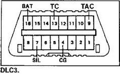
1, 3, 8, 9, 11, 12 Manufacturer option
2 J1850 Bus +
4 Body ground (CG)
5 Signal ground
6 CAN-High line, J-2284
7 K-line diagnostics (ISO 9141-2 and ISO / DIS 14230-4)
10 J1850 Bus
13 TC - Timing Check - Output for disabling the SPL correction for checking the base angle or output for reading slow ABS self-diagnostic codes
14 Line CAN-Low, J-2284
15 L-line diagnostics (ISO 9141-2 and ISO / DIS 14230-4)
16 Power supply + 12V from battery
Diagnostic connector pins for the protocols used.
Pins = 4, 5, 7, 15, 16 ISO 9141-2
Pins = 2, 4, 5, 10, 16 J1850 PWM
Pins = 2, 4, 5, 16 (no 10) J1850 VPW
All three communication protocols work through the standard OBD-II J1962 connector cable.
ABS - Troubleshooting:
Used to read self-diagnosis codes for additional vehicle devices
(Jumping "TC" and "E1" in the connector causes the codes to be indicated by the ABS, SRS, TRC OFF and Hight control lamps).
ABS - Read codes (models with DLC3 connector)
- Jumper the "TC" and "CG" pins of the DLC3.
- Switch on the ignition.
- After 4 seconds, read the code by the number of indicator flashes.
- Remove the jumper from the "TC" and "CG" terminals.
ABS - Reset codes (models with DLC3 connector)
- Jumper the "TC" and "CG" pins of the DLC3.
- Switch on the ignition.
- Press the brake pedal eight or more times within three seconds.
- The indicator should display the code of the norm (blink 2 times per second).
- Remove the jumper from the "TC" and "CG" terminals.
MANOOTI AZALIYA (Saturday, 19 April 2025 15:48)
Why does my premio not staring in the switch yet on direct it's working and it's relays,fuse and wirings are ok?
ابو غازي (Thursday, 17 October 2024 22:00)
شكرا جزيلا
Randy (Monday, 01 January 2024 07:44)
how do i check power supply i have something fryimg my altenators.
[email protected] (Thursday, 31 August 2023 14:01)
Obd
KANAND (Friday, 21 April 2023 10:42)
I like it